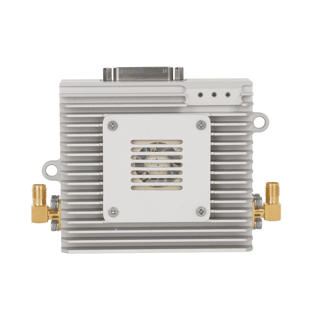
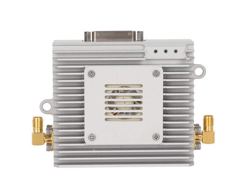
Ethernet: the payload backbone
Ethernet is the primary payload interface on every published model, from a single port on the waterproof and long-range units to dual ports on the J30 and 4KHD series. It carries IP video from network cameras, mission-computer traffic, and — on mesh models — the whole IP mesh payload.
Dual-Ethernet models typically separate payload from management, or bridge two devices such as a camera and a mission computer onto the same link. Check the model page for the port count; it is a hard physical constraint.
TTL/UART: telemetry and control
TTL/UART serial is the flight controller's native tongue on most autopilots: MAVLink-class telemetry in, commands out. It runs at logic levels, so keep the cable runs short and mind the voltage domain between module and autopilot.
Almost every published model exposes TTL/UART alongside Ethernet — it is the standard pairing of payload and control on one radio.
RS-232, RS-422, RS-485: the industrial serials
RS-232 appears on the J30, FrequencyHopping, and mesh series for legacy sensors and gimbal control — point-to-point, short range, tolerant of odd equipment. RS-422 drives longer differential runs; RS-485 adds multi-drop for daisy-chained devices.
The J30 series is the interface-richest family in the catalog (Ethernet ×2, RS-232, TTL/UART, SBUS, RS-422), which is why it anchors most integrations with several subsystems.
SBUS: RC passthrough
SBUS carries the pilot's control frames over the same radio as the payload. It appears on the J30, 4KHD, and mesh models. If manual override through the data link is a requirement, SBUS (or a serial equivalent) is the row to check.
Planning the port map
Write the port map before choosing the module, not after: one row per subsystem, its interface, its protocol, and the direction of traffic. Then check voltage (12 V/24 V aircraft buses vs logic-level serial), peak current at transmit, and connector style.
Antenna placement belongs on the same plan. An otherwise perfect interface map will not rescue a module whose antenna is buried under a carbon plate.